


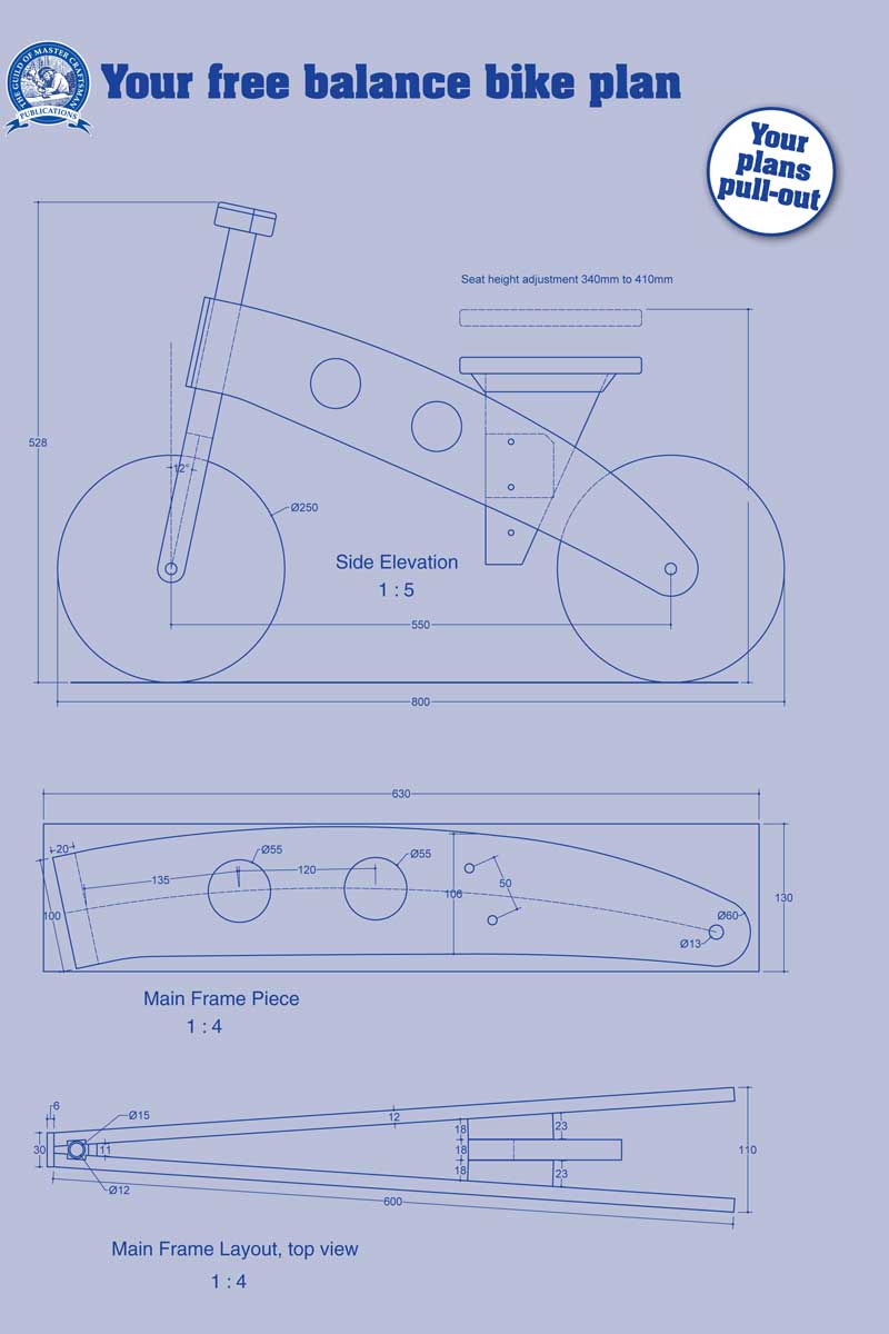
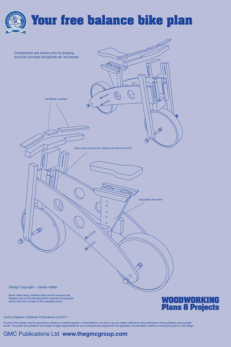
This bike is suitable for young riders. The seat adjustment allows the seat height to be in the range of 340 to 410mm, which should allow youngsters from about two to four years to make use of the bike. The design uses 12mm plywood for the main frame, and hardwood for the front steering assembly.
Designed for safety
Designing and constructing items for children means safety is of paramount importance. Clear guidance is found in the European Toy Standards EN71, and these rules must be adhered to.
Essentially, the structure must not use hazardous materials, or have features that can cause injury. These standards have been followed in the construction.
The materials used include plywood and hardwood - all edges have been rounded, and finished with a water-based varnish or paint with low volatile organic compound content (VOC).
The timber for the front forks and steering assembly must also be of a very high grade, close grained hardwood. I used mahogany here - this is to ensure that the steering assembly can stand up to the rigours of regular use.
The screws and other fixing items have had waterproof PVA adhesive added to give protection against becoming loose, as well as wood plugs in some places. The outside nuts used have a nylon insert to reduce the risk of loosening. The steering joint has been limited to ensure that it does not become a finger trap - and this can be further limited by adding plastic foam.
Having taken all steps to ensure the bike's safety, it must be stressed that it should only be used while there is a responsible person present, and a safety helmet should be worn by the user. In addition, the structure should have regular checks, and the tightness of any exposed nuts verified.
In addition, the bike is not intended to be used downhill, and is just for children in the correct age range, and being used on the flat.
The main expense when making your bike is the wheels - I've used plastic moulded ones with a diameter of 251mm. They have a hub width of 55mm, and a bore of 12.7mm. The present cost from Hobbies Ltd is £7.60 each. The spindles used for the moulded wheels and the steering spindle make use of a length of M12 studding. The studding is cut to the required length, and the ends rounded. In addition to wood screws, biscuits, adhesive, and nuts and bolts for joining, a cross dowel is used to secure the handlebar to the front steering column for added strength and safety.
Preparation
Step 1
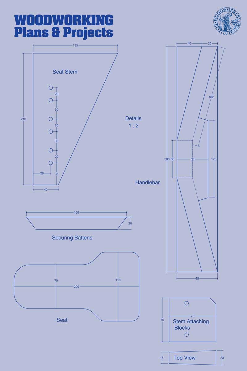
It is very helpful, but not essential, to make a full-scale drawing
Step 2
The advantage of using a full-scale drawing means an accurate template of the main frame pieces is produced. Alternatively, use the information provided to form the template
Step 3
Transfer the shape of the main frame piece on a piece of 12mm plywood
step 4
screw two of these together - first, cut the front at an angle of 12 degrees, and then use a bandsaw or jigsaw to cut out the required shape. Sand smooth, ensuring you take off the sharp edges
Step 5
With the two pieces still screwed together, use a 55mm hole saw to cut two holes - this will slightly lighten the frame, and also allow easier handling
Step 6
Check that the cut shape is accurate by returning to the drawing, if used. Mark and drill holes for the rear wheel spindle, and the seat securing bolts, as well as holes that will attach the front steering bearing
Step 7
Rebate a 12mm wide trench to a depth of 3mm, at the front end of each main frame piece. This will hold the plastic bearing for the steering pivot spindle. Varnish the pieces at a convenient time and use a safe water-based clear varnish, or paint if you want a particular colour
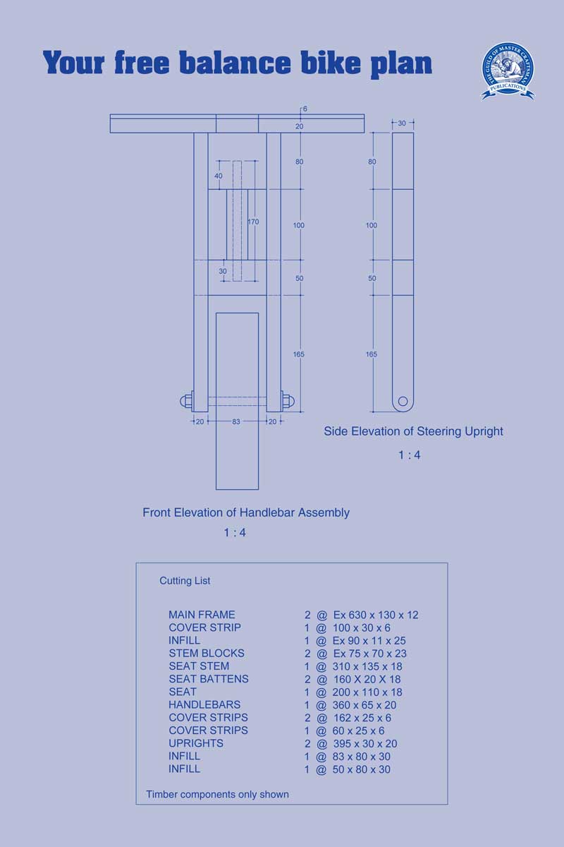
Steering assemblyStep 8
Next, cut the components for the front steering assembly. The top and bottom inserts both require a 12mm hole drilled to take the front steering spindle. Also, drill a 6mm hole from the top of the top insert, and a 10mm hole at the rear to take a cross dowel - this will be used to attach the handle bars later
Step 9
The two front steering uprights are joined to the top insert using size 20 biscuits and screws. The bottom insert is spaced 100mm below the top insert and is attached using screws
Step 10
Before assembling the front steering assembly, round over the outer edges of the uprights using a 25mm round-over bit in a router table. Also, round-over the section that will house the steering spindle. To assemble, first join each upright to the top insert using a single size 20 biscuit, waterproof adhesive, and a 4 x 40mm screw. The bottom insert is attached later
Step 11
For the rear wheel, cut a 145mm length of 12mm studding. Wind plumbers PTFE tape around the centre length of the spindle to fill the thread
Step 12
Feed the spindle through the wheel, with a nut and washer at one end. Place a washer on the other end followed by another M12 nut. Equalise the amount of stud either end
Step 13
Place a further washer on each end, and feed the rear ends of the main frame pieces onto the ends of the spindle - these are held in place using a washer and a nylon insert nut on either end. Adjust the nuts so that the wheel spins freely, and tighten the outer nuts when the assembly is completed
Step 14
Cut a 100mm length of 15mm plastic barrier pipe. The bore needs to be reamed to allow the 12mm spindle to rotate freely. Alternatively, use a length of 15mm copper pipe - the inner bore of this will allow free rotation of the spindle
Step 15
Moving to the front ends of the main frame pieces, run a bead of construction adhesive into the rebate. Place the plastic or copper bearing in the slot. Place the front end of the other main frame piece over the bearing, again with construction adhesive in the slot
Step 16
Secure in place using M6 hex head screws through to the nut inserts. Just tighten enough to hold together at this stage
Step 17
Cut a 170mm length of 12mm studding, or you could use plain steel rod if you have it. Rub candle wax along the part of the rod or studding that will be inside the pipe
Step 18
Insert the front infill just behind the securing screws with adhesive. Drive a couple of panel pins to hold in position. Push the heads below the surface and fill over. Now tighten the securing screws, but make sure that the spindle can still rotate freely. Add two 3 x 30mm screws to the front of the bearing. Use adhesive on the threads
Step 19
Finish the front edges of the main frame pieces by attaching a cover strip using 3 x 16mm screws and adhesive on each side
Step 20
To join the front steering assembly to the main frame pieces, place a washer over the top of the steering spindle, then insert the top of the steering spindle into the hole drilled at the bottom of the top insert
Step 21
Next, place a washer over the bottom of the steering spindle and using the bottom insert, engage the steering spindle into the hole. Push into place and check that the steering swivels freely
Step 22
Use two 4 x 40mm screws through either side of the steering assembly uprights into the sides of the bottom insert. Glue-up the insert and apply glue to the screw threads for extra security
Step 23
Cut a 155mm length of M12 studding, and wind PTFE tape around the centre length. Feed through one leg of the upright with a nut and washer in place, then screw through until the stud appears at the other end of the wheel hub. Fix another washer and a nut, and then continue to screw through so that the stud emerges through the other upright. Equalise and check that the wheel spins freely, then use a washer, and a nylon insert nut at each end, before tightening the whole thing up securely
Step 24
Cut the seat stem attaching blocks - they will require one face to be cut at an angle of 4 degrees
Step 25
Attach the blocks into position using adhesive, and a screw fitted between the two seat stem attaching holes. Drill through the blocks using a 7mm drill and make sure that the holes on both sides align
The seat
Step 26
The next stage is to make the seat. A simple seat can be cut to shape using a bandsaw or a jigsaw. Round-over the top edges of the seat using a 25mm round-over bit in a router table. Sand smooth, and make sure there are no sharp edges
Step 27
Cut the seat stem to shape, and cut matching size 20 jointing biscuit slots to join the bottom of the seat to the top of the stem. Drill the holes for the height adjustment securing bolts into the stem
Step 28
Cut two securing battens, and then join the seat stem to the base of the seat using size 20 biscuits and adhesive. Cut the front angle of the battens at 45 degrees and the rear at an angle of 70 degrees
Step 29Attach the securing battens either side of the stem using screws and adhesive. Align the end of the batten with the rear of the seat. Cover screw heads with wood plugs, and varnish the assembly and/or apply paint
Step 30
Insert the stem into position and align the holes to those drilled in the main frame pieces
Step 31
Feed the M6 bolts through and use a washer and an M6 nylon insert nut to secure each bolt. The height can be adjusted by selecting the appropriate pair of holes
Step 32
The handle bar has a base of pine, and the top has overlay strips of hardwood attached with adhesive. Attach the overlay strips using adhesive, apply weight and leave to set
Step 33
Cut out the rear of the shape with a bandsaw or jigsaw
Step 34
Round-over the hand grips with a 25mm round-over bit in a router table, and ensure all other edges are smooth. Drill the holes for the attaching screws
Step 35
The handlebar can be varnished prior to fitting. The one shown has a cream paint applied to the pine base, then over-varnished. Attach using adhesive, screws and a cross dowel
Step 36
Use a 4 x 45mm screw either side, and cover the screw head with a wood plug. Job done! The finished bike is now ready for action!
The cutting list for the project
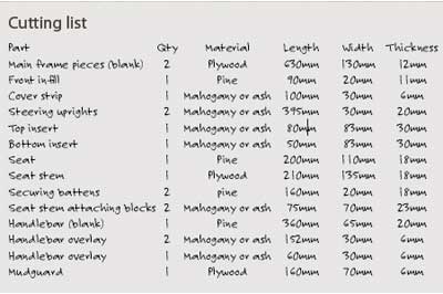
additional materials
1. 251mm diameter moulded disc wheels (WDW251) from
Hobbies Ltd
2. M12 studding ; 4 x M12 nuts; 4 x M12 Nylon insert nuts; 12 x M12 washers; 2 x M6 x 80mm coach screws; 2 x M6 nylon insert nuts; 2 x M6 washers; 100mm length of 15mm plastic barrier pipe; cross dowel screws M6 x 50; cross dowel M6 (77320); Insert nuts M6 - all from Screwfix Direct
No comments:
Post a Comment
Through these open doors you are always welcome